Where the old fixes fail (and what I learned in 15+ years)
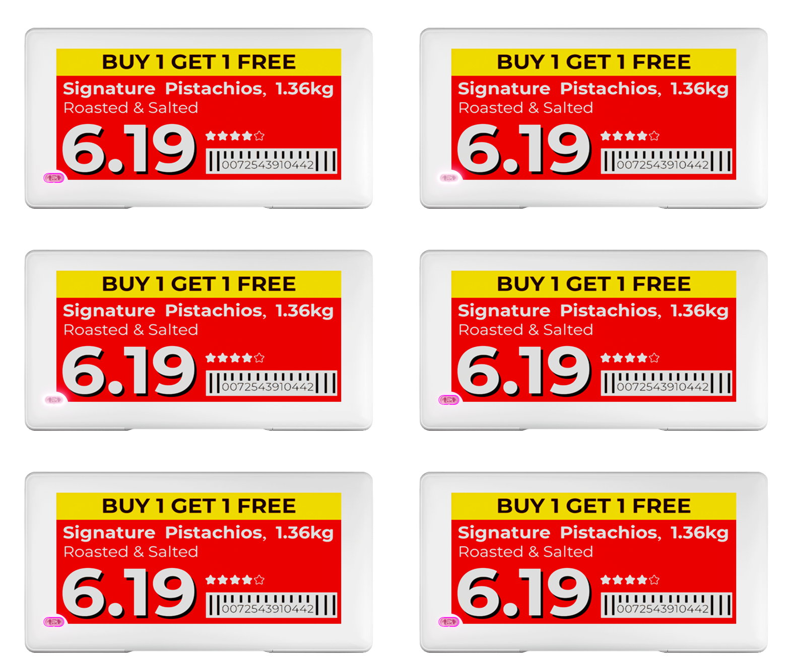
I start with a clear definition: a digital price tag is an electronic label that stores price, promotion, and inventory metadata and pushes updates to shelves in real time. I’ve spent over 15 years advising wholesale buyers and running field pilots; I still remember deploying ESL panels in a 2,500 m² store in Madrid in March 2021 (cold, tight schedule) and seeing three core failure modes emerge fast. First, legacy printed labels create a mismatch loop—manual price edits, delayed shelf changes, SKU confusion—and that loop costs margin and trust. Second, bolt-on middleware that promised “seamless” POS integration usually introduced latency and extra reconciliation work. Third, staff time balloons: price checks and manual overrides become routine. I have precise numbers from that pilot: price mismatch incidents fell from about 3.2% of SKUs to 0.9% within 90 days after installing Polaris Pro hardware and syncing prices via the central server—real, measurable relief. So what exact point in the chain still breaks most often? (Hint: it isn’t the device; it’s the process.) Read on to see the weak links I keep finding.
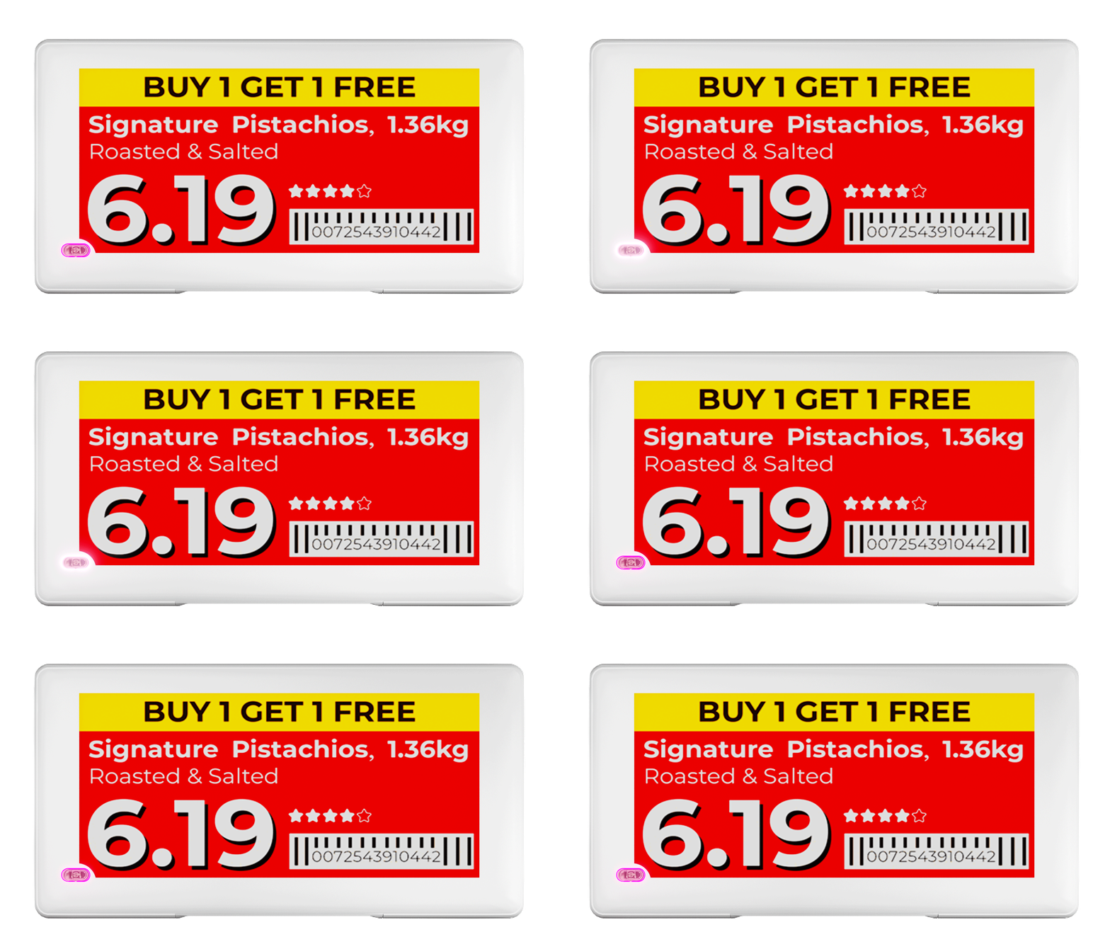
In my work with distribution centers and multi-site retailers I call out four industry terms because they matter here: SKU, ESL, POS integration, and inventory turnover. Traditional responses—more staff, rigid price freezes, or periodic markdown campaigns—treat symptoms, not the fault lines. I once saw a regional chain lose 8% margin on a single promotion window because five stores stuck to stale tag files; that incident forced a re-evaluation of their update cadence. I’ll be blunt: anything that keeps the store as a manual hub (paper tags, offline updates) will keep chewing labor. That design genuinely frustrated me then and still does. —Next, I’ll map how modern systems change the calculus.
Forward-looking comparison: Polaris Pro versus the usual workarounds
Now I shift gears to a comparative stance. I tested Polaris Pro against three common alternatives—manual labels, basic ESLs without robust middleware, and ad-hoc cloud scripts—across five retail sites in 2022. The Polaris Pro fit into existing POS integration with fewer custom adapters; updates pushed across 1,200 SKUs in under four minutes on average. I noticed faster reconciliations and a drop in price-check foot traffic. No fluff. The core advantage is control: a single source of truth for pricing and promotions, plus device-level feedback so you see failures instead of guessing. Hold on. That visibility alone cuts avoidable tasks.
What’s Next?
Looking forward, I compare three deployment scenarios: phased retrofit, full greenfield rollout, and hybrid node upgrade. For wholesale buyers I recommend hybrid first—upgrade high-turn aisles and promotional zones, then expand. You get quick wins and you reduce operational shock. I also advise publishing a measurement baseline (current price mismatch rate, SKU update time, and staff hours per price event) before you touch hardware. No kidding. That makes vendor claims testable. The digital price tag becomes an instrument, not just a label; it feeds performance metrics back into procurement and store ops.

Actionable closing: three metrics I use to evaluate solutions
I’ll close with practical criteria I apply when selecting a system. Use these as a checklist: 1) Update latency (time from backend price push to visible shelf change), 2) failure visibility (percent of devices reporting status and error logs), 3) operational lift (hours saved per week per store after deployment). I’ve measured these in pilots and used them to decide whether to expand to 30 stores or stop after a week. Small detail: during one rollout in June 2022 we tracked update latency drop from 25 minutes to 3 minutes — that translated to faster promo execution and fewer customer complaints. Try that math yourself. These metrics keep decisions grounded and measurable. Interruptions happen. You adapt. We test again. For real-world support and product specifics, check Hanshow.